
If you have any questions, you are always welcome to contact us. We'll get back to you as soon as possible, within 24 hours on weekdays.
-
Shipping Information
We offer reliable shipping across the United States. Orders over $599 qualify for free standard shipping.
Shipping options and estimated delivery times are shown at checkout and may vary by product and destination.
Products containing lithium-ion batteries may be subject to special shipping and carrier requirements.
For large equipment or enterprise orders, please contact our sales team for shipping assistance.
-
Customer Support
Need help choosing the right product, checking an order, or troubleshooting a product?
Our team can assist with product selection, order status, shipping, warranty, technical support, and general product questions.
Sales & Product Inquiries
Phone: +1 (888) 356-6818
Email: sales@droneroboticstec.comTechnical Support
+1 (888) 356-6818 Ext. 804 — Christopher
+1 (888) 356-6818 Ext. 806 — LucasWorking Hours
Mon–Fri: 9:00 AM–5:00 PM PST -
Contact Us
Have a question before placing an order?
Contact our sales team for product recommendations, availability, pricing, enterprise solutions, and bulk orders.
Sales Team
Phone: +1 (888) 356-6818
Email: sales@droneroboticstec.comFor enterprise, commercial, bulk, or dealer inquiries, we're happy to help you find the right solution.
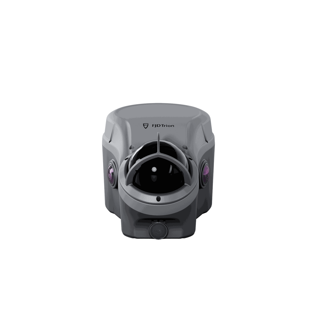
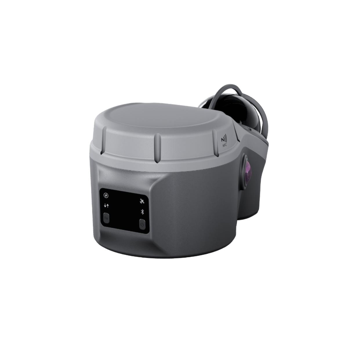
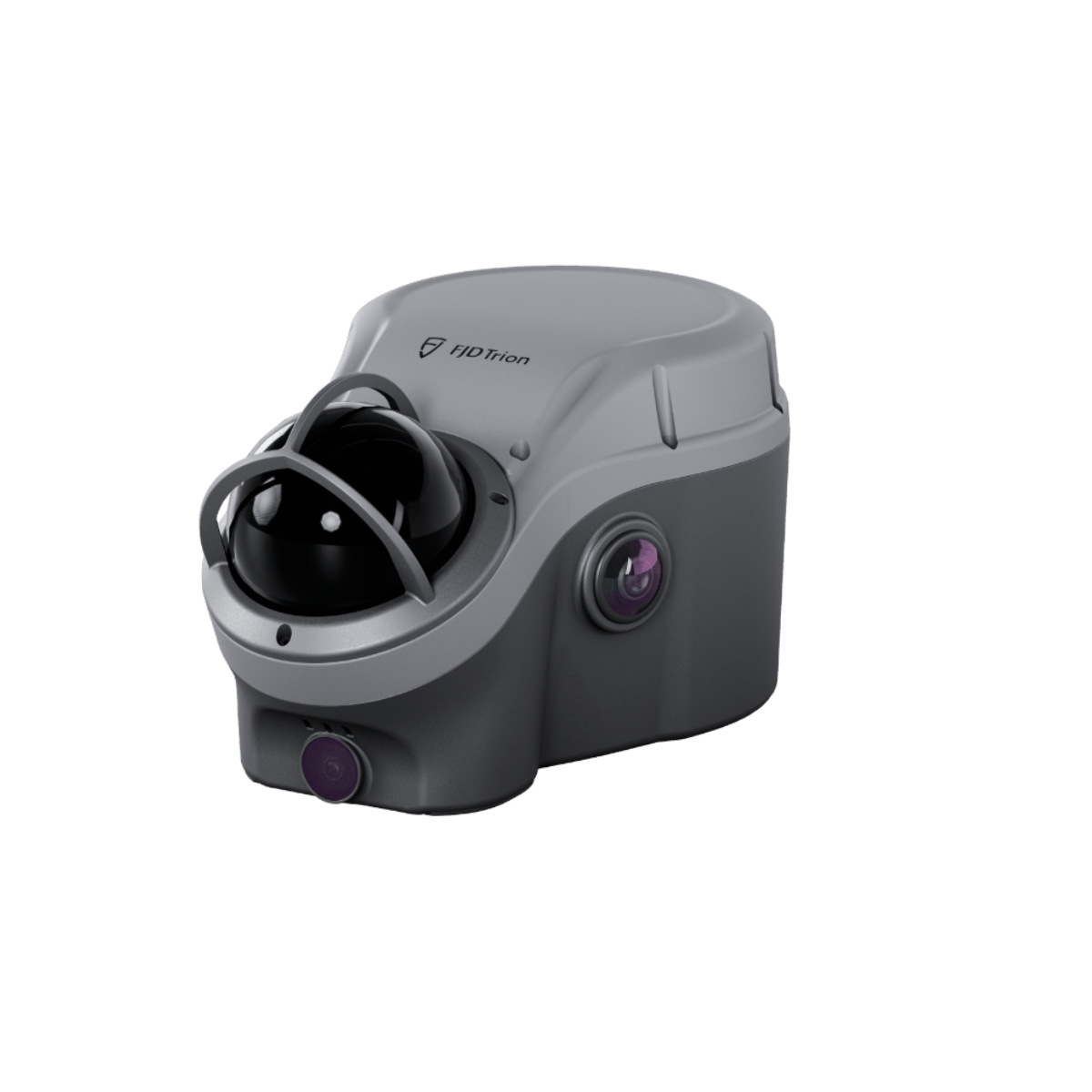
FJD Trion V100F GNSS LiDAR Fusion System
Combine GNSS positioning, 3D LiDAR scanning, imaging, and IMU in one integrated system for continuous, georeferenced spatial capture across open-sky, obstructed, and GNSS-limited environments.
From Point Survey to Spatial Capture
FJD Trion V100F combines GNSS surveying, 3D LiDAR, cameras, and IMU into a single field system. It is designed to keep measurement and spatial data capture moving as site conditions change, helping surveyors collect points, lines, surfaces, cross-sections, and volumes across demanding engineering environments.
Built for High-Performance Field Capture

*Specifications are based on FJD Trion published data and specified test conditions. Actual performance may vary depending on environment, surface reflectivity, satellite visibility, operating mode, and other conditions.
Four Technologies. One Field Workflow.
V100F brings positioning, scanning, imaging, and motion sensing together to create a unified workflow for georeferenced spatial capture.
GNSS
Multi-constellation GNSS positioning supports RTK, PPK, static, and other positioning workflows for georeferenced field data.
3D LiDAR
A 32-line LiDAR sensor captures surrounding geometry with a 360° horizontal field of view.
Cameras
Surveying, color, and bottom cameras provide visual references and support target selection and field verification.
IMU
Integrated motion sensing supports tilted RTK measurement and spatial data capture as the device orientation changes.
Keep Measuring When GNSS Conditions Change
Outdoor environments do not always provide uninterrupted satellite visibility. Bridges, culverts, tunnel entrances, urban canyons, and other structures can create GNSS-limited areas.
V100F combines GNSS, LiDAR, IMU, and imaging to extend field capture into nearby areas where conventional GNSS measurement may become difficult.
Typical ±5 cm @ 20 m Radius

SureFix is designed to maintain pole-based measurement continuity as you move from open-sky areas into nearby GNSS-limited environments.
Measure Difficult Areas Without Approaching Them
Capture targets from a safer distance in areas that may be hazardous, restricted, difficult to access, or inconvenient to reach directly.
Trench Edges
Select and measure trench boundaries without moving directly to the edge.
Wall Corners
Use captured imagery to identify targets and obtain LiDAR-based coordinates.
Under Bridges
Capture difficult areas without requiring direct access to the measurement target.
Slope Boundaries
Measure selected targets from captured images for field documentation and analysis.
Capture Tunnels, Culverts & Slopes in One Pass
Use the integrated LiDAR system to capture complex three-dimensional structures and generate spatial data for cross-section verification and engineering analysis.
From Point Clouds to Volume Results
Capture stockpiles, slopes, and earthwork sites and use FJD Trion Survey to perform volume calculations directly in the field.
Capture
Collect spatial data and point clouds in the field.
Process
Generate the spatial data required for measurement.
Calculate
Calculate stockpile, slope, and earthwork volumes.
Deliver
Review results and prepare project data for further processing.
Measure Without Keeping the Pole Perfectly Vertical
Integrated IMU technology supports tilt-compensated RTK measurement, allowing the system to maintain positioning performance when the surveying pole is tilted.
Visual Data Meets Spatial Data
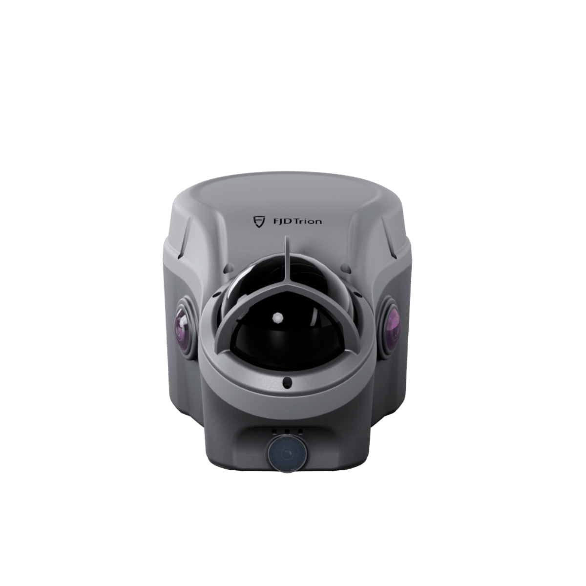
V100F integrates multiple cameras to support surveying, visual reference, target selection, and field verification.
Surveying Camera
73° H × 58° V × 87° D field of view for surveying and visual measurement workflows.
Color Cameras
Wide-angle color imaging supports visual reference and field target selection.
Bottom Camera
Additional downward-facing imagery supports field reference and device positioning workflows.
From Field Capture to Project Deliverables
Move from field collection to point-cloud processing, measurement, analysis, and project output through the FJD Trion software ecosystem.
Field Capture
Capture survey points, georeferenced point clouds, images, cross-sections, and field data.
FJD Trion Survey
Perform field measurement, review spatial data, and calculate applicable volume results.
FJD Trion Model
Process point clouds, review measurements, perform analysis, and prepare project outputs.
Deliver
Organize processed spatial data and prepare project-specific deliverables.
Built for Demanding Engineering Environments
V100F is designed for field conditions where surveyors need both precise positioning and three-dimensional spatial capture.
Urban Canyons

Capture spatial data where surrounding buildings can limit satellite visibility.
Mining & Earthwork

Capture terrain, stockpiles, slopes, and earthwork areas for measurement and volume analysis.
Tunnels & Underground Mining

Capture complex underground environments and generate spatial data for cross-section analysis.
Bridges & Viaducts

Measure areas beneath structures and capture difficult-to-access spatial targets.
Road Engineering

Support road surveying, terrain capture, cross-sections, and infrastructure documentation.
Utility Trenches

Capture trench edges and other difficult targets with non-contact measurement workflows.
Stay Connected in the Field
Multiple communication interfaces support flexible connection, correction, data transfer, and field workflows.
Technical Specifications

GNSS
| Specification | Details |
|---|---|
| GPS | L1 C/A, L1C, L2C, L2P, L5 |
| GLONASS | L1, L2, L3 |
| BeiDou | B1I, B2I, B3I, B1C, B2a, B2b |
| Galileo | E1, E5a, E5b, E6 |
| QZSS | L1, L2C, L5, L6 |
| NavIC | L5 |
| SBAS | L1 C/A |
| Positioning Rate | 1 Hz, 2 Hz, 5 Hz, 10 Hz, 20 Hz |
Positioning & Survey Accuracy
| Mode | Accuracy |
|---|---|
| RTK Accuracy | H: 8 mm + 1 ppm RMS V: 15 mm + 1 ppm RMS |
| RTK with Tilt Compensation | RMS: 8 mm + 0.6 mm/° tilt Tilt angle: 0°–60° |
| LiDAR Survey | Typical ±5 cm @ 20 m |
| SureFix Survey | Typical ±5 cm @ 20 m radius |
| High-Precision Static | H: 2.5 mm + 0.1 ppm RMS V: 3.5 mm + 0.4 ppm RMS |
| Post-Processing Static | H: 2.5 mm + 0.5 ppm RMS V: 5 mm + 0.5 ppm RMS |
| PPK Accuracy | H: 3 mm + 1 ppm RMS V: 5 mm + 1 ppm RMS |
| Autonomous | H: 1.5 m RMS V: 2.5 m RMS |
LiDAR
| Range | 40 m @ 10% reflectivity 60 m @ 80% reflectivity |
| Field of View | H 360° × V 62° |
| Number of Lines | 32 |
| Eye Safety Class | Class 1 |
Camera System
| Surveying Camera | 1 × 12 MP 73° H × 58° V × 87° D |
| Color Cameras | 2 × 12 MP 240° H × 240° V × 240° D |
| Bottom Camera | 1 × 2 MP 77° H × 62° V × 92° D |
Communication & Data
| Built-in UHF Radio | 410–470 MHz / 902–928 MHz 2 W transmit power Typical range 6–12 km; up to 16 km under optimal conditions |
| Bluetooth | Bluetooth 2.1 EDR / 3.0 HS / 4.2 BLE / 5.0 BLE |
| Wi-Fi | 2.4 GHz / 5 GHz, 802.11a/b/g/n/ac |
| Network Modem | TDD-LTE, FDD-LTE, WCDMA, GSM, EDGE |
| SIM | Nano-SIM |
| Data Formats | Output: NMEA-0183, RTCM 3.x, RINEX, LAS Input: RTCM 2.x, RTCM 3.x, CMR |
| Internal Storage | 450 GB |
General Specifications
| Operating Temperature | -20°C to +55°C (-4°F to +131°F) |
| Storage Temperature | -40°C to +75°C (-40°F to +167°F) |
| Humidity | 95% non-condensing |
| Ingress Protection | IP65 |
| IK Rating | IK08 |
| Battery | 14.8 V / 5,000 mAh / 74 Wh Li-ion |
| Charging | 45 W PD fast charging Approx. 3.5 h from 0–100% |
| LiDAR / Point Cloud Runtime | Typical 15 W, up to 5 h |
| UHF / 4G RTK Rover Runtime | Typical 3 W, up to 22 h |
| Dimensions | 215 × 130 × 120 mm |
| Weight | 1.75 kg |
| Display | 1.41-inch True-Color OLED 320 × 360, 274 ppi |